Written by Pat Hanrahan; updated by Julie Zelenski
Due: Tuesday, January 31 at 5:00 pm
Goals
Your next assignment is to build a clock using a 4-digit 7-segment display.
The goals of this assignment are for you to:
- Get started with bare metal programming in C on the Raspberry Pi.
- Begin building a simple modular library of useful functions.
- Learn how to write and use automated test cases to validate your code's behavior.
- Learn how to use the Raspberry Pi's system timer peripheral.
- Use your gpio and timer modules in the clock application.
Get starter files
Do a git pull in your $CS107E repository to ensure the courseware files are up to date.
$ cd $CS107E
$ git pull
Now cd to your local mycode repo and pull in the assignment starter code:
$ cd ~/cs107e_home/mycode
$ git checkout dev
$ git pull --allow-unrelated-histories starter-code assign2-starter
$ ls assign2
Makefile    cstart.c    larson.c    start.s     timer.c
clock.c     gpio.c      memmap      test_gpio_timer.c
In the assign2 directory, you will find these files :
- Files you will edit:
-
clock.c: your clock application program -
gpio.c,timer.c: library modules for the gpio and timer peripherals -
test_gpio_timer.c: test program with your unit tests for gpio and timer -
README.md: edit this text file to communicate with us about your submission
-
- Files you will use as-is:
-
Makefile: rules to build clock application (make run) and unit test program (make test) -
larson.c: sample application program for larson scanner (make larson) -
cstart.c,start.s,memmapare the support files needed for a bare metal C program. A bit later in the course, we will study these files to understand how they work and why they are necessary. Feel free to read over these files now to get a sneak preview, but don't worry if you don't fully understand them yet.
-
The make run target builds and runs the clock application
clock.bin. The make test target builds and run the test program
test_gpio_timer.bin, where you will add all of your unit tests. You will likely focus on using make test early in development and once your library modules have been fully vetted, move on to make run to test your clock application.
Just for fun, we also provide a program that implements the larson scanner in C using your library modules as an additional sample application.
Modular design
The gpio and timer modules provide access to two of the Raspberry Pi peripherals. The gpio module has routines that control the GPIO pins and the timer module retrieves the system tick count. The two modules are specifically used by the application program in clock.c, but, more broadly, these modules are designed to be reusable in any future application that requires similar functionality. These two modules are the first of many more to come. By the end of the quarter, you will have implemented a complete set of modules that form a library of core functions for your Raspberry Pi.
Each module is divided into an interface and its implementation. A module
interface is given in its header file e.g. gpio.h for the gpio module. In the header file, each public function is listed with its name, prototype, and documentation about what the function does. The implementation for the functions goes into the corresponding gpio.c file.
This idea of separating interface and implementation is fundamental to all software engineering: projects might have a different naming convention and file organization, but they always separate interface from implementation. Doing so abstracts away the implementation from a user, meaning that they can use the module without thinking about the underlying code that implements it. It also allows changing the implementation without causing any problems – this may become valuable towards the end of the course if you want to swap out your implementation for a reference one written by the staff.
For the gpio and timer modules, we specify the module interface; it is your job to write the module implementation to match it. You are not to change anything in the gpio.h and timer.h header files. All your edits will be in the gpio.c and timer.c source files. You should not export additional public gpio_ or timer_ functions. However, you can add your own private helper functions by declaring those functions at the top of the C file with the static keyword to make them only accessible to the implementation.
Where are the header files? The module header files are not a part of your local repo, but instead are stored in the shared directory
$CS107E/include. Change to that directory and list to see the filenames. Open a file in your editor to view its contents. You can also browse the header files here. Note that you should never edit/modify these header files, as they will not be included in your code submissions!
The file clock.c will contain code that you write to configure and operate
your clock. The clock application does not directly access the peripherals, but instead calls on the public functions of the gpio and timer modules. There is no required interface for the clock application, but you should strive for a clean and well-decomposed program that would make your CS106 section leader proud.
From here on out, each assignment will be structured in the same way: you'll implement a few library modules that an application program can leverage to accomplish some useful result.
Testing
The assignments in CS106B promoted testing using the SimpleTest framework; in CS107e, our poor man's version uses assert, but we all share the same approach: write lots of unit tests and use a test-as-you-go strategy. We know that learning effective testing strategies will serve you well throughout your life as a programmer.
The make and make run targets in the makefile are configured to build and run the clock application program. The alternate target make test will build and run the test program in test_gpio_timer.c. The first part of your work will be to write and test the gpio and timer modules and for this, make test is the appropriate target to use. When working on the clock application, use the make run target.
The test_gpio_timer.c is a program whose purpose is to run unit tests.
The main() function makes a series of calls to gpio and timer functions and uses assert() in order to validate the operations work correctly.
Recall from Lab 2 how assert() drives the red and green LEDs on the Pi as a simple status indicator. If an assert fails, the program stops and blinks the red LED of doom. If all asserts pass and the program finishes normally and the green LED of happiness will turn on. Your goal is to make that little green light shine!
The given test_gpio_timer.c only has a few very simple tests. You should
extend the test program with many additional tests of your own so that you thoroughly exercise the functionality of your modules. Unit-testing each module in isolation before going on to integrate its use into an application is an important strategy for managing the development process as your programs become larger and more complex.
Learning how to effectively test your code is an important component of growing your programming skills, and we want to be sure to reward you for your testing efforts. The breadth and depth of the test cases you add to test_gpio_timer.c will be assessed as one of qualitative metrics for your submission. But don't think of this as merely an arbitrary requirement to please your grader! Your investment in constructing a comprehensive set of test cases means you can find (and fix) more bugs, resulting in a submission of higher quality.
Core functionality
1. Implement and test gpio module
Review Chapter 6 of the Broadcom BCM2835 peripheral manual
which documents the GPIO peripheral. The device registers FSEL, SET, CLR and LEV will be used in your gpio module implementation.
When implementing a module, start by reading its documentation. Open the header file gpio.h (available as $CS107E/include/gpio.h or browse gpio.h here. The header file declares seven functions; each is documented with its expected behavior. Three of the functions are provided to you pre-written. Your task is to implement the remaining four functions according to the specification.
The first function you should implement is gpio_set_function. This operation is used to configure a pin to a selected function. As you recall from assignment 1, you configure a pin by changing the appropriate bits in its FSEL device register. When updating the bits, take care to not overwrite settings for the neighboring pins! This means you must first read the current state for all pins in this FSEL, selectively modify the bits of interest, and write back the updated state. In the Broadcom manual, this is referred to as "read-modify-write" operation. The FSEL registers are marked R/W in the table on page 90 of the Broadcom manual.
Next write the companion function gpio_get_function that returns the function a pin has been configured for. You obtains the current setting for a pin by accessing its bits in the FSEL register.
After implementing both set and get, you are ready to test your code. A simple first test case would be to configure a single pin using gpio_set_function and confirm that what is returned by gpio_get_function matches what was set. We write test cases using assert strategy you explored in lab2.
Open the test program test_gpio_timer.c and review the starter code version of test_gpio_set_get_function() to see a sample test case. Edit the main() and uncomment the call to test_gpio_set_get_function(). Use make test to build and execute the test program. If the green LED on the Pi turns on and stays lit, the test program ran successfully – bravo! If instead the Pi's red LED is flashing, this means an assert failed. If neither LED lights up, your program may be freezing or crashing somewhere during the tests. (Review testing exercise of lab2 for more information).
Passing this test is a good beginning, but this provided test is only a sample to get your started. You will need to add many test cases of your own to thoroughly exercise your code and confirm the full range of functionality. Here is a partial list of the expected features, each of these features corresponds to one or more test cases:
- get the pin function should match what was set
- can configure a pin to input, output, or alternate functions
- refer to
gpio.hheader file for valid options
- refer to
- a pin can be re-configured
- e.g. set to output then set to input changes pin from output to input
- can configure any pin from entire range of GPIO pins
- the Pi has a total of 54 GPIO pins, spread across six FSEL device registers
- see yellow note below about testing pins with special function
- each pin's configuration is independent of others
- access to a pin's configuration should not interfere with configuration of other pins
What other cases can you think of to add to the above? As you add each new test case, build and re-run your test program to verify success.
Your functions should also be robust against client error. If given an invalid pin or function, do not blunder on to sadness. The function documentation in the gpio.h header file gives specific guidance on the expected handling for improper calls. Once you have implemented that handling, add further test cases that confirm it is working as intended on such calls.
Pins with special function When writing test cases, take note that certain GPIO pins have specialized operation.
- GPIO 14 and 15 are used for serial transmission and by default have the function
GPIO_FUNC_ALT5. Manipulating these pins will disrupt the communication between your computer and the Pi. You do not need to include GPIO 14 and 15 in your tests.- GPIO 35 controls the red power LED on the Pi and GPIO 47 the green ACT LED. If you manipulate these GPIOs, the corresponding LED will be affected. This is to be expected.
The gpio_write and gpio_read functions read and write the current pin state. To set a pin's state to high, write a 1 to the corresponding bit in its SET device register, to set low, write a 1 to corresponding bit in its CLR device register. Writing a 0 to SET or CLR has no effect. To read a pin's state, test that bit in its LEV device register. By separating access to set, clear, and level, there is no need for a read-modify-write operation as was required for FSEL. In the table on p. 90 of Broadcom manual, the SET and CLR registers are marked W (write-only), LEV is R (read-only). Attempting to read from SET or CLR or write to LEV will result in undefined behavior.
After implementing the functions, you are ready to test. The test program test_gpio_timer.c has a sample test in test_gpio_read_write() that calls gpio_write to change the state and confirms that gpio_read returns the update state. Consider what additional behaviors need to be confirmed and write test cases for each:
- read should match value that was written
- can read and write pins across entire range of GPIOs
- each pin's state is independent of others
- proper handling of invalid calls
Don't forget that observing the GPIO activity is another way to confirm correctness. An implementation of gpio_write and gpio_read that are both broken in same way could theoretically pass a round-trip unit test, but observing an LED light or registering a button press is the real deal.
Now bathed in the green light of your now-comprehensive test cases for the gpio module, you have completed your first Raspberry Pi module – Congratulations! 🏆
The gpio module is a key component of the library you are building. Several of the modules you will implement in later assignments will layer on gpio. Given your efforts to thoroughly test and vet the module, you will be able to confidently rely on it going forward!
A note on volatile Writing code that correctly interacts with a peripheral will require understanding of the
volatilekeyword. Consider this pointer to the memory-mapped GPIO device register LEV0:unsigned int *lev = (unsigned int *)0x20200034;The data at that address can, and should, be qualified as
volatile:volatile unsigned int *lev = (unsigned int *)0x20200034;A
volatile unsigned intindicates the value can change due to events not apparent in the code.*levaccess the current pin state through the device register. Whether the state is 0 or 1 depends on what is physically connected to the pin, which can change externally. If C code repeatedly reads from*levwith no intervening write to the location, the optimizer could make the assumption that the value will not change and cache the value of the first read and re-use it later. If type is qualified asvolatile, the compiler cannot make that assumption and must re-read the value for each and every access.
Note thatvolatileis not something to throw about willy-nilly. Apply it thoughtfully and intentionally to those specific data values that need to be treated in this special manner. Extraneous use ofvolatilecan be misleading and will reduce performance as it disallows the compiler from making optimizations. Review the recommended readings on volatile from C Pointers lecture on the Schedule page.
2. Implement and test timer module
When implementing the clock, we'll need to determine the passage of time. Thankfully, the Raspberry Pi includes a "system timer". The system timer is an on-board peripheral that is initialized to zero when the Pi powers up and is continuously incremented once every microsecond behind the scenes.
Chapter 12 of the Broadcom BCM2835 Peripherals Manual contains the documentation for the system timer peripheral. For this module, we only use the lower 32-bits of the system timer. Don't forget that we use ARM physical addresses, not bus addresses (0x7E… for peripherals), so you'll need to change the 0x7E… prefix in any peripheral address to 0x20.
The timer module provides functions that access the system timer. Read the header file timer.h to view the function declarations and module documentation. Review the provided code for the module implementation in timer.c.
You have only one task for the timer module which is to implement the function timer_get_ticks to read the current system tick count. This one-liner will be a piece of cake for your now-experienced bare metal self!
Uncomment the call test_timer() in test_gpio_timer.c. Use make test
to build and run the test program. Verify the given tests succeed and then consider what additional tests are needed for the timer module (there may not be much; it is a pretty simple module). Once both the gpio and timer modules are passing all of your tests, you're ready to tackle the clock application.
3. Wire up and test clock hardware
Next turn your attention to the hardware for your clock display.
- Complete the breadboard circuit for the 4-digit 7-segment display you started in Lab 2. Test your breadboard with jumper cables so that you know the wiring is correct before you connect it to the Raspberry Pi.
- In total, you will use 13 GPIOs on the Pi: eight pins to control which segments
are on, four to control which digits are on, and one to read the state of the
start button. Here is the schematic from lab (click to enlarge):
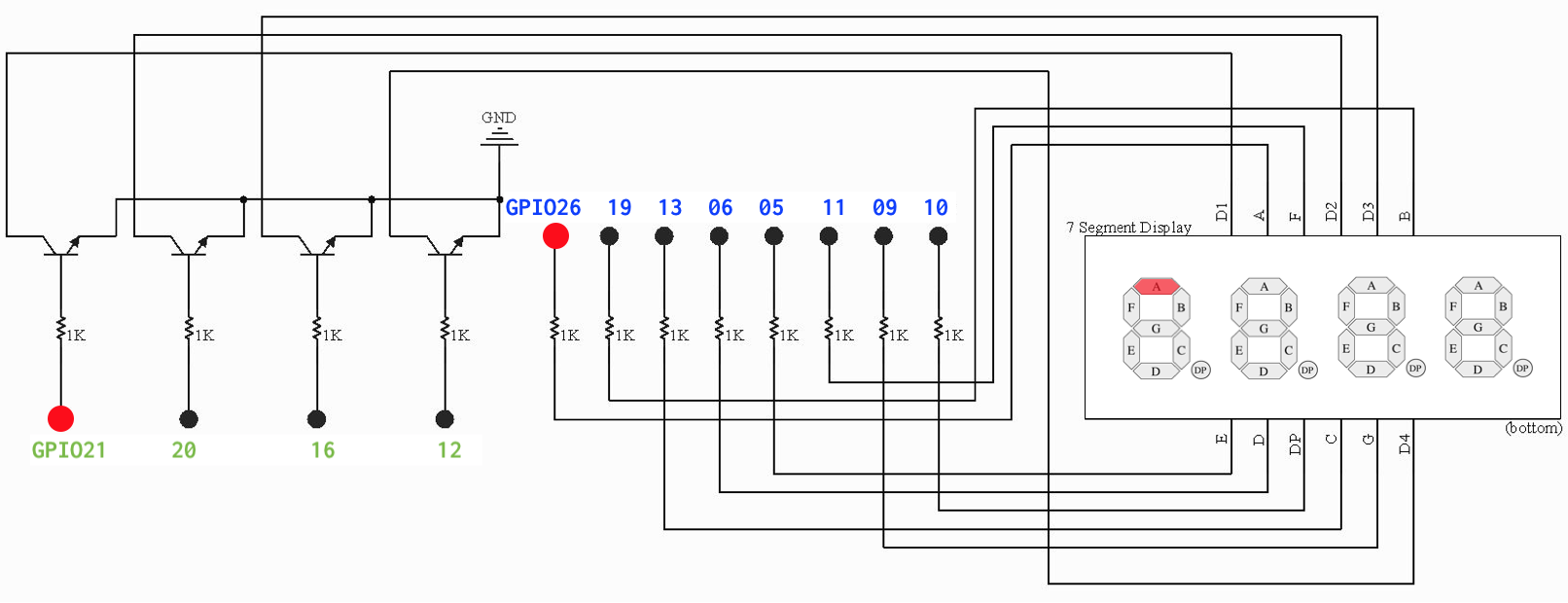 The assigned GPIOs appear to be random, but if you compare it to the pinout, I think you'll see the method to our madness.
 - The dots labeled in blue text are the segments. Connect the seven GPIO pins
{26, 19, 13, 6, 5, 11, 9}to the 1K current-limiting resistors on your breadboard that drive segments A through G. GPIO 26 controls segment A, GPIO 19 controls segment B, and so on. An 8th pin, GPIO 10, can be used to control the decimal point, which is optional. - The dots labeled in green text are the digits. Connect the four GPIO pins
{21, 20, 16, 12}to the base of the transistors controlling digits 1 through 4. GPIO 21 controls the first digit, GPIO 20 the second digit, and so on. - Connect GPIO 2 to your start button. The start button should be connected to the power rail through a 10K pull-up resistor; pulling the default state high. Pressing the button grounds the circuit, bringing the reading low.
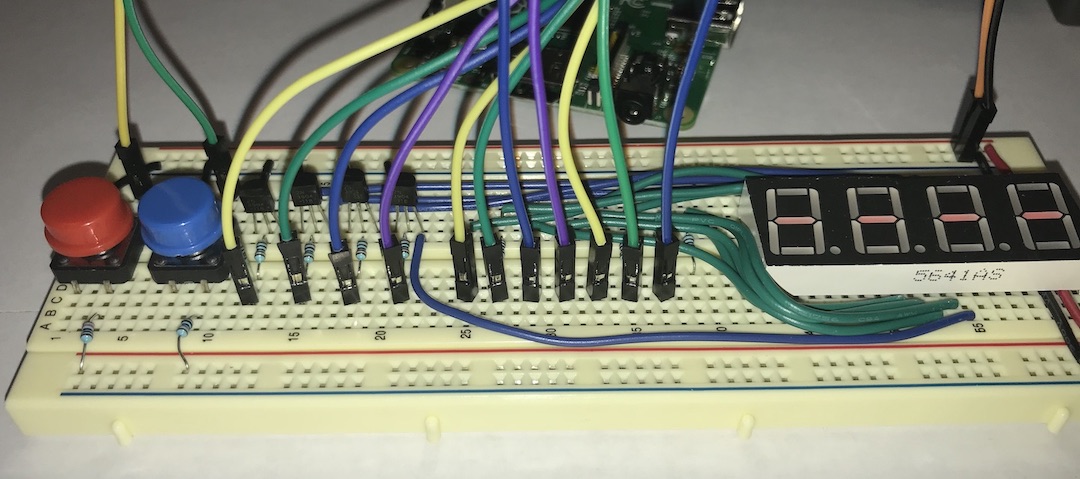
- Here's a photo of our clock breadboard connected to the Raspberry Pi.
We selected jumper colors in a repeating pattern (yellow-green-blue-violet) to help identify which connection is which.
After wiring up your breadboard, you want to test all those connections and your shiny new gpio and timer modules are just what you need. In the test_gpio_timer.c there is a test_breadboard function. This test calls your gpio functions to configure the pins, and goes into a loop which flashes the segments one by one, exiting the loop when the button is pressed. Uncomment the call to test_breadboard and use make test to build and run the test program and visually confirm the operation of your display and fix any missed connections. Give yourself a pat on the back for your marvelous gpio module – imagine how much harder it would be to manually test each of these connections!
Snap a photo of your finished hardware setup, copy the file to the assign2 directory in your repo. Add and commit the file to include it with your submission. We want to see your beautiful handiwork!
4. Display a digit
You are now ready to start on the software for clock application.
In clock.c, create an array of 16 elements, one for each hexadecimal value between 0 and 15. Each array element should
be a byte (8-bits). C has no byte type, but unsigned char suffices. Bit 0 (the least significant) will represent segment A, bit 1
segment B, and so on. If a bit is set, then that segment should be lit. For example, digit 0 consists of segments A-F, so its bit pattern is 0b00111111. Digit 1 consists of just segments B and C, so its bit pattern is 0b00000110. (0b is the prefix that introduces a binary number literal, just as 0x prefixes a hexadecimal literal)
Bit 7 (the most significant) will be used to represent DP, the dot. Since we won't be using the dot in this assignment, bit 7 should always be 0.
Create bit patterns for all the digits 0, 1, 2, 3, 4, 5, 6, 7, 8, 9, A, B, C, D, E, F. You won't be displaying A-F for this assignment, but they may be useful in the future. This interactive demo of a 7-segment display is handy for seeing how the bit pattern relates to the character segments.
Write a function that display a single digit and call it from the main() function of clock.c. Verify that your bit patterns are correct by displaying each digit value from 0 to F and visually confirming.
Use make run to build and run your clock application.
5. Write display refresh loop
The GPIO pins that drive the seven segments A to G are shared by
all four digits on the display. There is no way to turn on the display segments to show a 5 on the leftmost digit while simultaneously showing a 3 on the rightmost digit.
Instead of actually displaying a simultaneous 5 and 3, you'll accomplish the same effect with a display refresh loop that iterates over the digits one-by-one in quick succession. It turns on the segments for the leftmost digit, waits a moment, and turns off those segments, then repeats the process for each of the other three digits. You might think that turning a digit on and off would cause it to flicker. The key is to sequence through the digits so fast that our eyes cannot see them changing. Good thing computers are fast!
Implement the display refresh loop in clock.c. Use the functions from
the timer module to control the wait time. Loop though all four digits, turning each on for 2500 microseconds. Do you see any flicker? How long does the delay have to for you to start to see it?
6. Implement clock
The clock program starts by showing ---- on the display and
waits for the user to click the start button. Once started, the clock counts the elapsed minutes and seconds since start. A loop continually refreshes the display, updating the value displayed to match the elapsed time. Confirm that the timer is calibrated correctly by observing that the clock is counting at the right rate according to your watch or computer.
The clock time is counting elapsed time since the clock was started, which is not quite the value as the system tick count. Clock time and the system tick count change at the same rate, but start at different values. Your program will need to implement this logic.
This video shows starting our Raspberry Pi clock and counting to 12 seconds:
Mission accomplished! You have wired up a complex breadboard circuit, written two reusable library modules and a clock application, as well as working up a methodology for testing your code. Be sure to show off your spiffy new clock to your followers (but not to the TSA next time you pass through airport security…).
Troubleshooting
Here are some problems that have "bugged" students in the past, presented here to help you troubleshoot if your code isn't working:
- To express a number as binary constant, prefix it with "0b", e.g. 0b10110001.
- Make sure you declare variables that read/write from/to the peripheral registers as "volatile", otherwise the compiler might optimize away repeated reads/writes. If you don't understand why this is important, ask us in lecture, lab, or office hours – it's important and also pretty cool!
- Make sure you are wiring to the correct pins! On the pinout diagram, there is a gap row of two pins without labels, and sometime students have counted labels rather than the individual pins, resulting in wiring to the wrong pins.
Extension: Set time
If you're looking for an extra challenge, consider doing the optional extension to create an interface to set the clock time.
Before starting on the extension, be sure you have completed all core tasks, including commit, tag, and push of your completed code. This ensures your submit tag is a known good place that can be a fallback if the extension doesn't pan out.
The extension follows the same workflow, edit files on the dev branch, make regular commits and pushes. When you have successfully completed the extension, tag with assign2-extension so we know you to grade your extension.
Add a second button to your clock breadboard next to the start button. Connect this button to GPIO pin 3. Design a user interface that allows you to set the time using these buttons. The user should be able to set the minutes and seconds separately. The time must be settable before starting the clock, able to be changed after the clock has started running, and able to re-set an arbitrary number of times (i.e. not just once initially). While setting the time, the display should change in some fashion to show it is in "set" mode; perhaps by flashing or scrolling a banner message on the display? Be creative! Strive for an interface design that is easy to use and provides clear feedback to the user. It can be challenging to build an interface with just a few buttons.
When reading button presses, you will quickly realize that pressing the button once may cause the value on the GPIO pin to fluctuate several times. This is due to physical characteristics of the button mechanism which cause the button circuit to rapidly jitter between open and close multiple times before settling down. To address this issue, you should implement debouncing to discard those spurious events and process as a single press. When you observe the value has changed, follow-up with additional reads to confirm that value has stabilized. Experiment with the amount of time required to register a valid press so that your buttons click easily without having to hold them down too long, but do not generate extra button press events for a single physical button press.
Add documentation to the README.md file for assign2 that explains to the user how to set the time via your buttons.
Submitting
When submitting, your assign2 directory should contain:
- a photo of your completed breadboard
- implementations of the
gpio.candtimer.cmodules - comprehensive tests for both modules in
test_gpio_timer.c - application program
clock.c -
README.md(possibly empty if you did not do the extension)
Submit your finished code by commit, tag assign2-submit, push to remote, and ensure you have an open pull request.
The steps to follow are given in the git workflow guide.
Grading
To grade this assignment, we will:
- Verify that your project builds correctly, with no warnings.
- Run automated tests on your
gpioandtimermodules. - Observe your clock application running on a Raspberry Pi wired to a clock breadboard and visually confirm its operation. Our hardware setup will be configured exactly as specified above.
- Admire the photo you submit of your completed breadboard.
- Go over the unit tests you added to
test_gpio_timer.cand evaluate them for thoughtfulness and completeness in coverage. - Review your code and provide feedback on your design and style choices.
Our highest priority tests will focus on the core features for this assignment:
- Essential functionality of your library modules
- Set/get the function on any valid pin
- Read/write to any pin
- Reading the timer value, controlled delay
- Clock application
- Correct display of count of elapsed seconds over time
The additional tests of lower priority will examine less critical features, edge cases, and robustness. Make sure you thoroughly tested your for a variety of scenarios!
Note: Build warnings/errors We expect your code to compile cleanly with no warnings or errors. Warnings are the way the compiler draws attention to a code passage that isn't an outright error but appears suspect. Some warnings are mild/harmless, but others are critically important. If you get in the habit of keeping your code compiling cleanly, you'll never miss a crucial message in a sea of warnings you are casually ignoring. The provided makefile is set to treat warnings as errors, and your code will be graded in the same way.
Our grading process
-
After the due date, we run automated grading tests against the submissions and CAs do the qualitative reviews. We give feedback on your pull request and use GitHub issues to report tests that were not passed.
- Our grading tests are organized by priority. Higher priority tests are considered more significant in grading.
- P1 "Essential" tests exercise core functionality that is critical to the system's operation. Your system won't be fully usable until these high priority issues are addressed.
- P2 "Comprehensive" tests thoroughly exercise the full range of functionality including lesser-traveled features.
- P3 "Just Mention" is used for small concerns as a misbehavior in an obscure edge case or minor issue of polish.
-
We have a revise and retest policy for library modules. We will file GitHub issues for each test failure that is eligible for revision, and you may submit bug fixes for retest. Commit and push changes to your repo on your
devbranch and tag the finished commit withassign2-retest(Do not move the originalassign2-submittag!) Once a week, the staff will re-run the automated tests on submissions taggedassign2-retestand update to show passing results on issues that were corrected. - We accept revisions for priority 1, 2, and 3 automated tests on your library modules. We do not accept revisions for extensions or tests that are manually evaluated (all of A1 and the clock tests for A2). These tests will only be run against your original submission, marked with the
assign2-submittag.
By the end of the quarter, we expect your library modules to have passing results on all Priority 1 tests. Lower priority tests and tests on non-library modules can be fixed at your discretion, but are also taken into consideration when determining final grades.
Good habits == good results
We encourage you to consciously develop habits that will serve you well in this course and going forward. Here are a few we recommend you start today:
- Practice with your tools and work to establish comfort with your environment. Be alert to where you have rough spots in your workflow,and make an effort to smooth it out. This might take the form of learning additional editor features, becoming more facile with the command-line, or customizing your environment more to your needs. Share your tips on Ed and ask for advice from others!
- Make frequent git commits to record a snapshot of your ongoing work. This gives you an audit trail of your progress in your local repo and each commit is a place to compare or return to should anything go astray. When at a clean stopping point, use git push to sync your local history to your GitHub remote repo. You can think of your remote repo as your "off-site" backup that ensure that all of your hard work is safely recorded.
- When writing unit tests, do not comment out tests to de-activate them once you have confirmed they are passing. If you keep previous tests active so that they execute on every future run of the test program, this alerts you if you accidentally introduce a regression, i.e. a change causes a previously passing test to now fail.